FE- Modelling of bolt connections under axial load
Generally seen the FE analysis of bolt connections may provide advantages in terms of time and expense over testing the connection and can provide a more accurate result concerning of stress, strains and force distributions than any other methods. However, the existing potential of the method will be not always realized, because the result from finite element analysis, especially in the case of screw connections can be extremely sensitive to modelling technique. In the event of the bolted connections is this particularly true.
Realizing that the FE method is an approximation to reality, the success of which is dependent on gaining good and overall balanced judgments on different topics, it is important to be able to create a FE model without compromising the accuracy of the model in comparison to the required effort time.
Inclusion of the screws in finite-element models simulates real behavior. The impact of the bolt is decisive to the behavior of all parts in the connection.
Especially during the modelling, one realizes how complex a screw connection is. Starting from the task of bolted joints, to hold the different parts permanently fixed, i.e. under all operating conditions and loads, the features of the FE modelling are beginning with the fact that the bolt connection is a pre-tensioned connection and can only function properly as such. Both features pretension and mating part contact require extremely subtle modelling for the purposes of accurate FE-analysis.
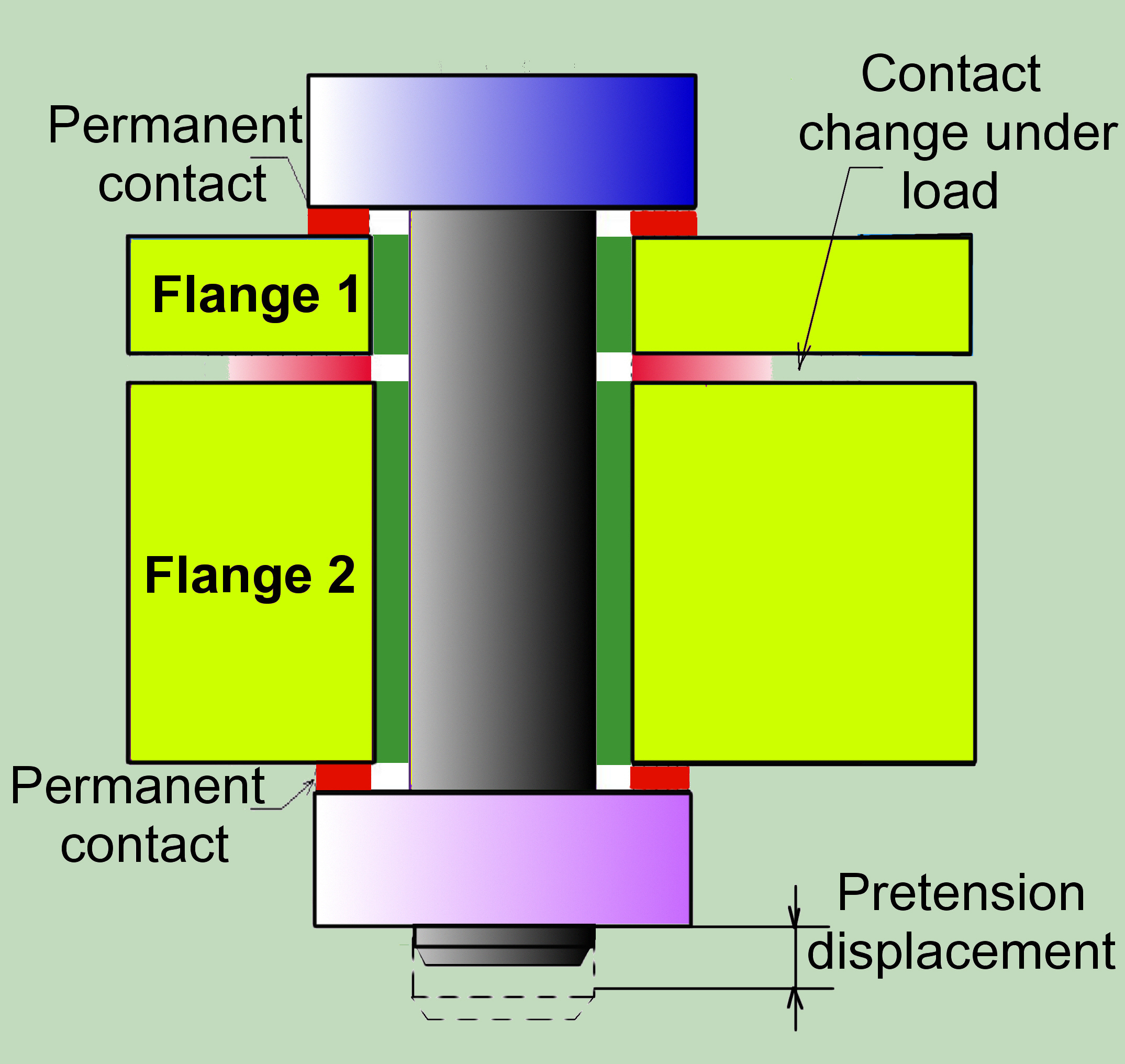
Nevertheless, due to the given complexity, the possible simplifications are imperative. The question is which are possible and suitable.
From a simulation standpoint, the surfaces in contact, which change under load, must also be able to separate. Here, the contact elements that are capable of discrete contact are used.
However, the contact elements in the contact surfaces between the flanges and the head/nut of the bolt, in which the permanent contact is to be expected in most cases, are not required. Unfortunately, this claim is not always true. If the section is too much weakened by the bolt hole or the bolt is too stiff, linking could appear and the bolt can be in contact only on one side. In case of shear-loaded connection, it is also necessary to consider at this place the frictions relationships. Generally, the non-consideration for one or the other feature is an engineering judgement, which implies knowledge of the connection behaviour under given operational conditions what can be achieved by a parallel analysis using adequate analytical method, as proposed on this site.
Either FE or analytical modelling of the total multi-bolted joint is generally not necessary and this is also not practical and would detract from the basic task. It may be sufficient to model a single fastened structure segment, with boundary conditions carefully chosen to replicate the constraint existing in the actual joint. The fastener segment is then loaded with a force representing the local pre-fastener force under whatever complex, non-uniform loading situation that occurs. Bearing on the latter, however special care has to be given to the fact that the multi-bolted connections are statically undetermined. Symmetric conditions, as cyclic symmetry, could be practiced only if the following two conditions are met: Geometry is symmetric and boundary conditions (including forces and constraints) are symmetric.
Due to the local form of the connection, the final modelling should be based on a solid bolt simulation. To ensure that the FE mesh is fine enough and that the contact conditions are adequately solved, it is necessary to check everything.
In the FEA simulation, it would be unusual to model the full thread engagement between the bolt and the nut. Highly detailed 3D models that simulate this effect are possible ( CMC Bolt), but they are extremely computationally expensive and pretension is very sensitive to correct friction properties and geometric inaccuracy. It is more useful and much more convenient to carry out hand calculations that are used for margins on threads, based on screw load (forces and moments) from FEA results.
Because we cannot model what we cannot quantify, some effects cannot be (or only limited) considered within FEA, as for example: geometry imperfection effects, initial embedding in assembly, sequence effects during assembly of multi-bolted connection.
Preloading during assembly of the connection
Standard bolting systems involve a bolt preload. During assembly, we apply torque to turn the nut for bolt pretension. Theoretically, we can use the angle through which the nut turns, instead of torque, to control pre-load. Finally, when we turn the nut on a screw by 360º, the screw retracts with a linear displacement equal to exactly one pitch of the threads. Hence, yet though we speak about preload force, what we do is the introduction of the preload displacement by turning the nut alongside the bolt threads.
In a real word, joint members may not be absolutely flat and there may be a bent washer so that the starting position for the value of the amount of turn required varies unpredictably, even between apparently identical bolts or joints. In an FEA simulation, we do not have to worry about this. However, it is crucially significant to realize the art of preloading by displacement introduction in the interrelated system bolt-related components. It should not come as a surprise that one of the first methods available to realize this in FEA was through thermal contraction of the screw.
To apply the pretension, we need to know the relationship between the displacement and the required preload force and the appropriate position for the introduction of this displacement.
The deformations within a joint can be taken from the so-called joint diagram.
Tension diagram is a popular and useful graphical representation of the behavior of bolted connections, showing the relationships to external stress, bolt and plate stiffness, bolt force, member residual clamping force i n the joint, and the joint separation.
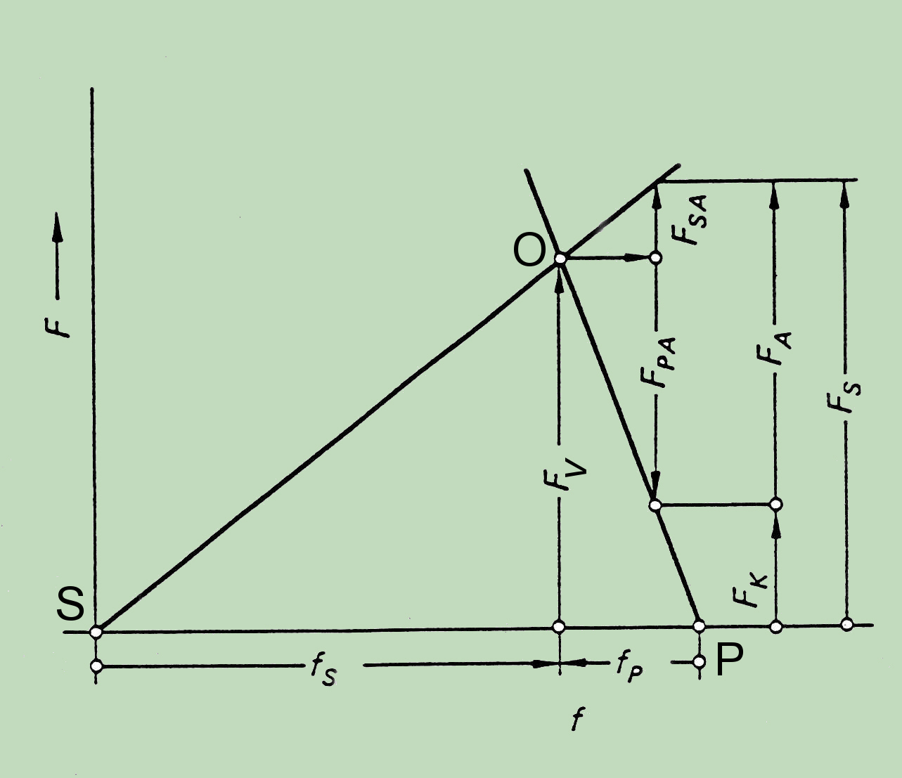
The relationship between the assembly preload and the elongation of the bolt is represented by the bolt curve, which is nothing other than the spring characteristic of the screw bolt. The slope of the corresponding line is dependent on material and geometry. When the bolt is tightened, the bolt extends along the line SO by fS (see figure). The reaction force (the right hand side of the graph) is the clamp load of the joint and the joint compresses as shown by the line PO for fP. In this instance, bolt tension is equivalent to the preload, which is equivalent to the joint compression. Therefore, the deformation of the joint, realized by turning of the nut, necessary for required preload force is the sum fS + fP.
This will change with the application of an external load. If a concentric external load FA is applied under the bolt head and nut (same Figure), the bolt elongates an additional amount while the compressed joint members partially relax. This coupled change of the deformation with external force is the key for the interaction of forces in screw connections. The results of the FEA will be only adequate if this interaction of the forces is maintained under all conditions.
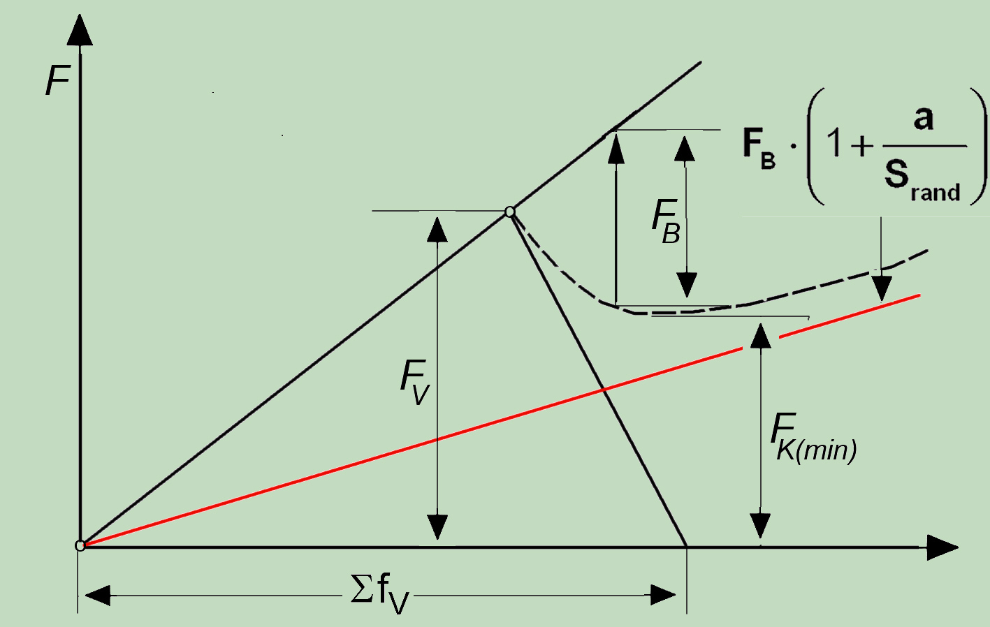
In the case of an eccentric load connection, the situation, however, is much more complex than shown by this simple tensioning diagram. Due to the eccentric external force, the reaction force in the joint is also driven to the edge so that the leverage effect (red in the figure) leads to the considerable overloading of bolt in the connection. After reaching FK (min) the connection no longer works and all parts are loaded over proportionally.
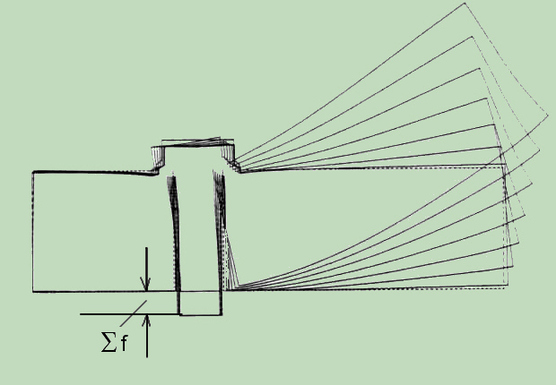
If, based on symmetry, just one half of the connection is modelled than the introduction of the preload displacement is, as shown in the figure, relatively simple. The preload is realized by an initial strain of bolt part against the symmetry line. The picture also shows how the initial strain remains unchanged for all stages of the load on the compound.
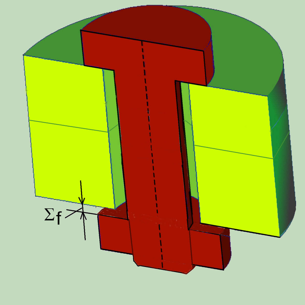
For complex connection, pretension can generally be modelled with constraint equations, or a special form of nodes coupling. Instead of the direct coupling of the nodes, equations are used which, between the assigned nodes, simulate the creation of a constant initial elongation of the bolt shaft. In some FEM (MARC, ABAQUS), such boundary conditioning procedures (TYING) are automated for the user.
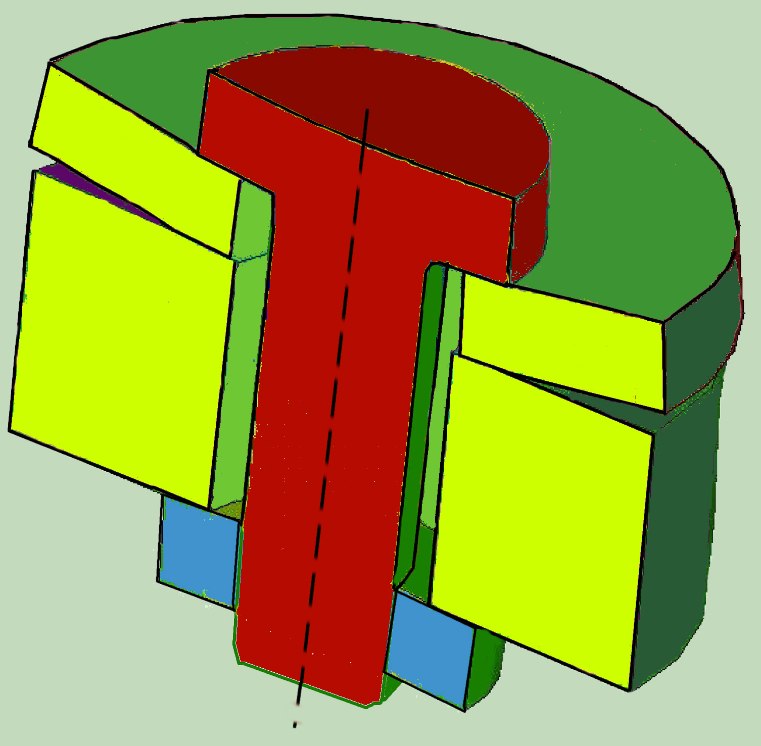
This can be imagined as the introduction of an infinitely stiff disk at this point, with the thickness given by the preload displacement.
Some FE software already has a built-in tool for simulating the bolt preload.
In the case of a cylindrical connection, particularly when the thickness of one of the connected parts is low, the separation between the surfaces in contact may also be possible during the prestressing. This will also reduce the axial stiffness of the joint.
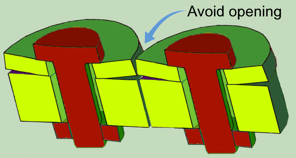
However, if only one sector of the multi-screw connection is modelled, this behavior must be suppressed at the boundaries to the adjacent sector by the appropriate boundary conditions to ensure continuous displacements.
Finally, in the case of multi-screw connections, if only the modelling of the most heavily loaded sector is used, it should not be forgotten that the global stress redistribution depends on deformations, which are non-linear and therefore also non-linear.
Typical formulas as for example for flange or plate cover and the like
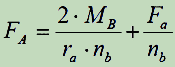
has, although generally on the safe side, not a universal application and should be verified through the additional investigations.
Return to top
Zurück zu den Schraubenverbindungen